
This Workshop has Spelt Enjoyment! — 1943
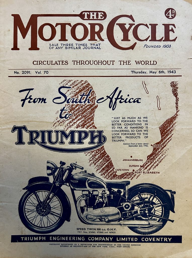
In May 1943, The Motor Cycle published this three-page article by my grandfather, John Davies, describing his home workshop and the remarkable rebuilding of a 150 c.c. New Imperial motorcycle for approximately £1.
At the time, Davies was working as a senior examiner for the War Office, and the article reveals that his working days included “testing armoured fighting vehicles.” Away from that work, engineering remained his great personal passion.
The article is particularly valuable because Davies also looks back on his earlier life: sitting astride his uncle’s motorcycle as a boy, taking his first motorcycle ride at fourteen, joining the Navy, his years abroad, Egypt, and his return home in 1925.
The original copy of The Motor Cycle, dated 6 May 1943, survived among the papers and possessions of his daughter, Christine. It is reproduced and transcribed below.
This Workshop has Spelt Enjoyment!
A Reader-enthusiast describes his well-equipped Workshop, which has Cost Comparatively Little, but Provided Endless Pleasure! How a 150 c.c. New Imperial was Completely Rebuilt for £1
By JOHN DAVIES
[Magazine photograph caption]
What can be done with enthusiasm plus ingenuity. Here is a corner of the author’s workshop showing his 3in. screw-cutting lathe mounted on an old mahogany sideboard. The set of castings from which the lathe was constructed cost £3 15s.; the sideboard cost nothing! A lorry flywheel and an Austin Seven axle casing go to make the treadle.
WHEN “Nitor” paid me the compliment of visiting me a few weeks ago and looking over my small workroom, it was suggested that I should give a brief description of how the workshop originally began and the work that has been carried out in it during those too-brief evenings and days off from my place of work. Although I do not claim it to be a motor cyclist’s dream workshop, many happy hours have been spent “tinkering about”—as my good wife was wont to call my endeavours.
It all started many years ago when I first sat astride my uncle’s single-speeder and kidded myself that I was a real motor cyclist. I was about ten years old at the time; my first actual ride was on an old single-speed Triumph of about 1910 vintage when I was 14; and then came the war to end wars, and I joined the Navy as a boy. I have travelled a good deal since those days, and in my wanderings have picked up a few bargains here and there in the form of those tools that go to make the subject of this article.
Bought Off the Stalls
On my discharge in 1925 I bought my first motor cycle—a J.A.P.-engined Mohawk, two-speed and chain-cum-belt drive, which I converted to three-speed all-chain drive a couple of years later and eventually sold. It was during this conversion that a number of tools were picked up off the stalls in the local market, and real bargains they turned out to be. One item was a No. 6 Jacobs drill-chuck with key for 2s. 6d., a bundle of old reamers (high-speed steel) for 7s. 6d.—and so I could go on. I must mention that off the same stall a rule was bought for 9d., which fitted a Starrett protractor-head I had brought home from Egypt. When visiting my father in France, I completed the set by finding among his equipment a square that fitted!
I have found that a certain amount of discretion must be used when buying tools; for instance, all the spanners I use are good ones; it is better to buy one good spanner than two at the same outlay. On the other hand, my 1in. micrometer cost me 15s. at a large tool stores in Reading. For my occasional use it has proved very satisfactory, but it would obviously be useless in a toolroom in use all day and every day.
The 3in. back-geared screw-cutting lathe, shown in the photograph was constructed from a set of machined castings advertised in a model engineering journal in pre-war days. The set of castings cost £3 15s.; this included a face-plate, and the set of change-wheels. The chuck, a 3in. Bernard, was bought new for £1 7s. Several alterations were made during the course of construction. These include the rack and pinion, an apron cut from solid which houses a double-clasp bronze nut actuated by an enclosed cam, the graduated tailstock and double knurled lock-nuts to the headstock mandrel. This lathe was originally mounted on a chaff-cutter stand (with the works taken out, of course!). The “power-house” was evolved from an Austin Seven axle casing, a lorry flywheel, a light car front hub turned down to fit the centre of the flywheel, the hub running on ball bearings with a piece of Ford steering column as a spindle, and the “pitman” consisting of two magneto sprockets and a piece of cycle chain; the sprocket on the adjustable throw is bolted up solid, while that on the treadle is fitted with a bush. If you have ever caught your foot under a treadle with a solid pitman you will understand why I have adopted this scheme.
The flywheel weighs 120 lb. Starting and treadling are very easy, and the latter can be kept for a considerable time. For the belt I use a piece of rein.
I intend carrying out further improvements to the lathe when time permits. Micrometer feeds will be fitted to the slide handles, and also an overhead drive for milling. This latter will be driven from the large diameter of the headstock cone—something similar to the “Booths” overhead gear. At present, small milling cutters for keyways are made from silver steel and held in the chuck, the work being held at centre height in the tool post.
The local contractor, hearing that I had a lathe, came to me last year with a couple of armatures. Would I skim the commutators down and undercut the mica for him? Half an hour’s work and the job was done. How much? “Oh, that’s all right; perhaps you can do me a favour one day.” A few days later: Could I reface a set of valves?
One Good Turn Deserves . . .
I returned the valves one Sunday morning while out for a walk. Up in the corner of his garage was a 7ft. sideboard. Did I want it? If so I could have it, and gladly. Did I want it? You bet I did. It was complete with drawers, doors, sliding panels and a nest of baize-lined drawers that originally held cutlery. It was duly delivered; with it came a neat marble washstand. The marble top was replaced by plywood—I was frightened of its weight—and the table is used as a storage place for the components for my new machine. It did not take long to scrap the old lathe stand and substitute the sideboard in its place. Now I have a neat stand for the lathe and every tool is to hand, with still room to spare for more.
The other photograph shows the workbench. It needs no description, except to say that I have been promised an old cottage piano that will one day take its place.
As my workshop is the spare room, it is always kept in fairly presentable condition, and only those pieces that I am working on at the moment are allowed to encumber the bench or lathe.
I have been a keen motor cyclist since returning home from abroad, and owned several machines up to the start of this war, when I was forced to abandon the sport through family reasons. I had to take to cycling. This did not go down too well—I have five miles to go to work each day and am away from home for most of the daylight hours testing armoured fighting vehicles. So when a workmate offered me a couple of worn-out 150 c.c. New Imperials I took them; but on seeing their condition I almost thought of putting them on the scrap-heap. However, I stripped the two machines down to the last nut and bolt. Each piece was examined and the best pieces were put by to start on. One big-end bearing was good, and also one frame. I have a few old races in good condition, and these were sorted out to find those suitable. I found one main bearing and one small bearing for the gear box mainshaft.
The crankcases were taken in hand first. The timing side bushes were in fair condition, so they were left. The place where the oil retainer behind the sprocket had worn the aluminium away I filed off flat, and faced it with steel secured by three 4 B.A. countersunk screws. The main bearing was shrunk into position, and the bearing from the clutch wheel centre was used as the gear box mainshaft bearing. I adopted a tip from “The Motor Cyclist’s Workshop” to ensure that the big-end bearing got plenty of oil. A hole was drilled through each flywheel to act as jets for the oil picked up by the flywheels; this has proved very satisfactory. This work completed that on the bottom half of the engine.
The barrel I had rebored by a friend in the trade to take a standard Morris Eight piston; there was plenty of metal in the barrel for this. End-caps were made from bronze for the gudgeon pin, and a new small-end bush was made to suit. The piston was fitted with two compression rings and one scraper. The lower compression ratio I have since found is perfect for Pool. Valves were cut from some taken from a 30 h.p. Rolls-Royce, and Hillman guides were turned down to suit. New tappets were made from the solid, and case-hardened. The camwheels were slightly worn; they were left, for I have no means of grinding cams.
[Magazine photograph caption]
The author says that his workshop must be kept presentable because it is in the spare room. However, one has a shrewd idea that such a keen enthusiast would keep it meticulously neat in any case. This glimpse of the workbench shows how all the tools are kept readily to hand. The small drawers and cubby-holes are invaluable.
The small timing pinion was originally bought for the Mohawk-J.A.P., and never used. This pinion was a taper fit; it was ground out parallel to fit the new shaft. What is that about “keep a thing for seven years and you will find a use for it”? The original pinion was much wider in the teeth than the camwheels. The J.A.P. pinion was only the exact width of the camwheels, so I made up a washer to go behind this pinion to make up for this difference in width. With these alterations the pinion fitted perfectly.
Swapping Cam Spindles
I did intend to fit the contact-breaker so that it ran off the exhaust camwheel spindle, but finally decided on the fitting of a magneto. The original engine had the contact-breaker on the end of the dynamo, and this ran at engine speed. For this conversion the camwheel spindles were pressed out and the cams were interchanged, i.e., the inlet became the exhaust and the exhaust the inlet. Why? Because the inlet cam spindle was keyed to the wheel, and I did not want my ignition to play any tricks. So the force fit of the inlet spindle in the exhaust camwheel was relied on to drive the oil pump, and a new extended spindle was made for the exhaust camwheel to drive the magneto. This sounds very involved, but in reality it is quite simple: Inlet originally keyed; inlet not now keyed. Exhaust originally not keyed; but now keyed. Got it?
The pump boss on the timing gear cover was cut away so that the magneto drive sprocket cleared it. The front engine plates were slotted and a magneto platform made up. A small B.T.H. mag. was installed à la A.J.S. in front of the cylinder. The magneto chain was enclosed in a case beaten out of aluminium sheet. Other bits and pieces were as follows: Magneto chain and sprockets ex Norton; new cam spindle made from a Sunbeam foot-brake spindle; the magneto built up from pieces from four old ones; foot-rest hangers, ex Norton—they have bosses welded to the bottom of the engine plates and filed to suit, which gives a fine adjustment. The carburettor was made up from pieces from three. The kick-starter return spring was originally, I think, an Enfield rear-brake pedal return spring; the cover for it was cut from the top of a Ford cut-out. A new gear box sprocket was cut from the solid, turned to the dimensions of the original, the splines filed by hand. A 17-tooth Matchless engine shock absorber sprocket was used as a jig for drilling and filing the teeth. Case-hardening finished the job. The oil spinner behind the clutch was scrapped and an oil-thrower substituted.
The clutch corks—large round discs—are a joke in this house. My wife thought for a long time that the youngsters had lost those two big cork mats that Daddy used to put his dinner plate on!
For lighting, a pal gave me a voltage-control dynamo from a Magdyno. The armature was removed and the driving end turned taper shape to take the bronze driving wheel. The ball-race in the end had to be ground down 3/32in. on the outer face. The pear-shaped piece on the end was scrapped, and its place was taken by a 2½in. round recessed disc that acts as both oil excluder and ball-race retainer; it is fitted with a cork packing to make an oil seal against the primary case. The regulator was fitted under the saddle, wired up to an 8in. head lamp of the Lucas type. The battery was given me by a workmate.
New steering-head bearings were made. Fork spindles were made from silver steel, and a new right-hand bottom to take A.J.S. friction discs and a hand adjuster.
And it Worked!
Timken taper bearings were used in the front wheel. These bearings were originally 10-thou. oversize from what I wanted, and were ground down in an unorthodox manner. The bearing was assembled, held in the hand and offered up to the hand grindstone and allowed to revolve with the wheel—and it worked! Micrometer measurement showed that there was hardly .00025in. difference all round. The bearings were pressed into the hubs, and a new spindle was made to suit the races.
To complete the machine a pair of B.S.A. plated handle bars with bolted-on controls and a B.S.A. toolbox were fitted. The secondary chain was a ½in. by 3/16in. heavy carrier cycle chain. Tyres fitted were 3in. front and 3.25 rear. Fuel consumption worked out approximately at 100 m.p.g.
Why did I take all this trouble? For the experience gained, for the pleasure it has given—and to own a fairly reliable bike. I now get to work fresh as a daisy in ten minutes—a job that used to take half an hour of hard work (and a minute lost meant a quarter of an hour’s loss of wages). The cost of the rebuild, excluding tyres but including the rebore, was approximately £1. As the machines were given me I feel I have a very reliable machine at a very low cost!
I have recently bought cheaply another machine of the same make, but a later edition. I have also undergoing renovation a 1914 two-speed Douglas and a 1905 four-cylinder single-speed shaft-drive F.N.
[Magazine photograph caption — page 314]
In these days of furniture shortage, many will wonder at a mahogany sideboard used as a lathe stand. At the time it was put into use such an article was almost unsaleable. It is extremely useful, with drawers, doors, sliding panels and a nest of baize-lined drawers. On the left is a battery-charging set, consisting of a dynamo driven by a little air-cooled side-valve engine; it is extremely neat. Incidentally, if the battery to be charged is not flat, it can be used for starting the engine, the dynamo then being employed as a motor.
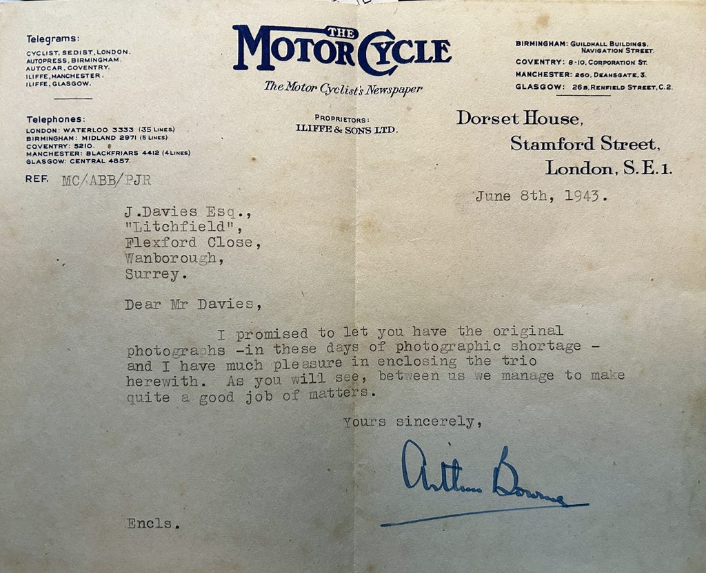
A month after the article appeared, Arthur Brittan Bourne, editor of The Motor Cycle, wrote personally to John Davies, returning the three original photographs used for the feature.
His brief letter, dated 8 June 1943, provides a fitting postscript to the article — particularly his comment:
“As you will see, between us we manage to make quite a good job of matters.”